[Arduino Uno] analogRead / analogWrite
Created:
Updated:
analogRead / analogWrite
In the Arduino Uno board, there are 6 pins A0 ~ A5 that can read analog input voltages, and their resolution is 10 bits. That is, the min/max value of the input voltage is reprresented from 0 to $2^{10}$ which is 1023.
The reference voltage used for analog input is 5V by default for “5V Arduino board”, and 3.3V for “3.3V Arduino board”. To change the analog reference voltage, we can change it using the analogReference() function.
Analog output can be output through the pin marked ‘~’ among digital pins. These pins output the PWM type waveform, which outputs the following type waveform. Depending on the duty cycle ratio, the HIGH/LOW interval of the PWM waveform is determined. And as this waveform is outputted quickly, the output voltage level is determined.
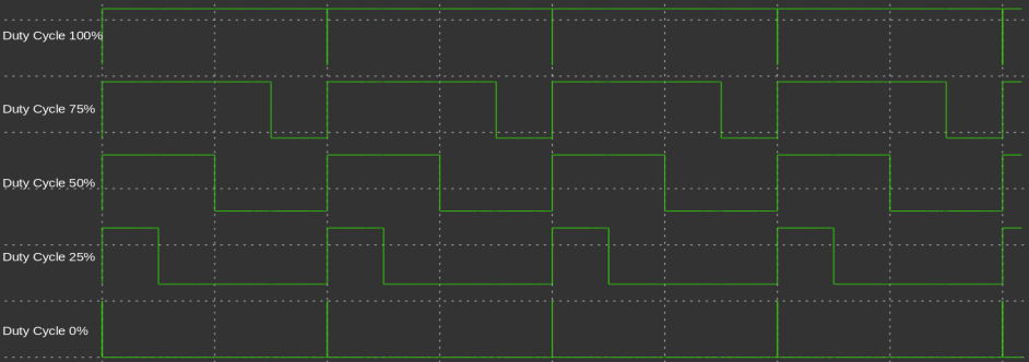
The range of analogWrite is 0 ~ 255. That is, when the reference of the analog reference voltage is 5V, 0 ~ 5V is referented as 0 ~ 255.
circuit
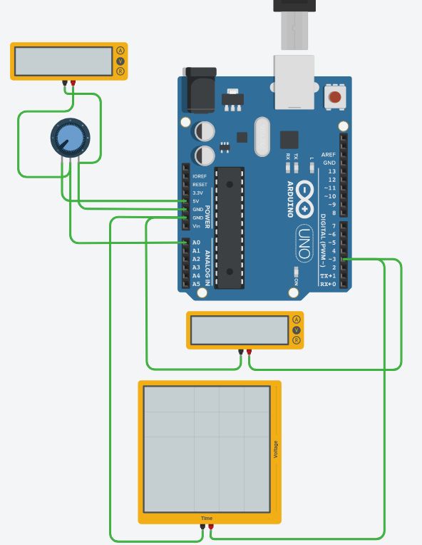
In the circuit below, it shows that the voltage changes according to the change of the potentiometer with the voltmeter. Also, analog input values can be checked through serial output, and output voltage levels and output waveforms can be viewed using a voltmeter and an oscilloscope.
In this example, the analog reference voltage was not changed, so the test was performed in the default setting(here, the reference voltage is 5V).
Therefore, the input voltage 0 ~ 5V is expressed as a value of 0 ~ 1023.
There are 3 pins on the potentiometer. Connect pin 1 to max input voltage(5V here), pin 3 to ground, and pin 2 to analog input pin of Arduino Uno board. Here it is connected to A0.
code
1
2
3
4
5
6
7
8
9
10
11
12
13
14
15
16
17
int analogInputPin = A0;
int analogOutputPin = 3;

void setup()
{
  pinMode(analogInputPin, INPUT);
  pinMode(analogOutputPin, OUTPUT);
  Serial.begin(9600);
}

void loop()
{
  int readValue = analogRead(analogInputPin);
  Serial.println(readValue);
  analogWrite(analogOutputPin, readValue/4);
  delay(1000);
}
In this code, analog input is expressed in the range of 0 ~ 1023, and analog output is expressed in the range of 0 ~ 255, so readValue/4 is used as the output value of analogWrite().
execution
In this video, when the potentiometer is changed and the input voltage becomes 700mV, the analog input value is 143. When it is 2.5V, the analog input value is 511. When it is 4.2V, it is 859 and when it is 5V, it is 1023.
The analog output(D3) voltage and its waveform are also changed according to the input voltage. It can be seen that as the analog input value increases, the duty ratio of the analog output waveform increased.
Leave a comment