[Arduino Uno] 7-Segment Display
Created:
Updated:
7 Segment Display
7 segment is a module representing a number in an embedded system. The number is divided into seven segments and represented by one LED per segment. This means that seven LEDs represent a single number and this is called 7 segment display. One more LED is used to represent decimal point.(So, there are 8 leds in total). In order to use 7 LEDs, ‘+’ and ‘-‘ pins are required of for each LED, so a total of 14 pins are required. Depending on the connection method, ‘+’ or ‘-‘ pins are generally used in common. If ‘+’ is used in common, it is called common anode, while ‘-‘ is used in common, it is called common cathode. The figure below show the general structure of 7 segment display, the left side show the common anode and the right side shows the common cathode.
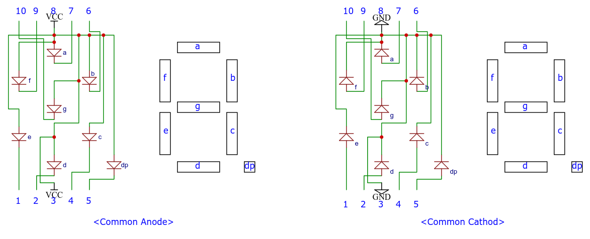
In case of common anode, the LED of 7 segment is turns on if the ‘-‘ pin of LED is LOW, and it turns off if it HIGH. In case of common cathode, the LED of 7 segment is turns on if the ‘+’ pin of LED is HIGH, and it turns off if it LOW. Since the circuit varies depending on the common anode and common cathode, so be careful not to make mistakes.
For ex)
- To represent ‘1’ with the common anode type, the ‘b’ and ‘c’ segments must be 0, and the rest must be ‘1’.
- To represent ‘1’ with the common cathode type, the ‘b’ and ‘c’ segments must be 1, and the rest must be ‘0’.
The pin number may vary depending of the manufacturer, so you must check the datasheet of the 7 segment.
Common Anode
circuit
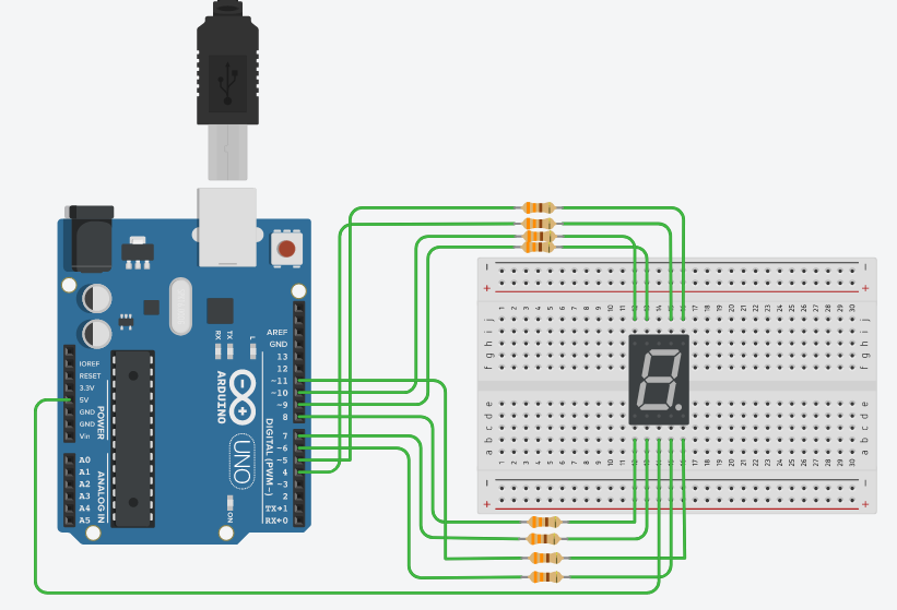
This circuit used 7 segment of common anode type, so “5V” is connected to the common pin, and a resistor for controlling the amount of current is connected to the pin of each segment. In case of each LED’s forward voltage is 2V and to ensure the current per LED does not exceed 20mA, the calculation is done by the I = V/R formula. 0.02A = (5V-2V)/R, So, 150 ohm can be used as the result of the calculation. But we have one more thing to consider. The datasheet of Atmega328P used in Arduino Uno has the following contents.
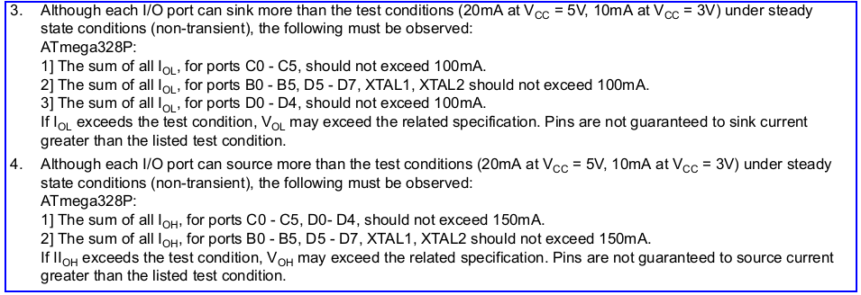
So, in order to comply with this condition, a current smaller than 20mA must be flown. here 330 ohm(under 10mA) was used.
The forward voltage and the peak forward current that allowed for 7 segment differ according to the 7 segment type, so you must check them in the datasheet.
| Arduino pin number | 7 segment pin number |
|---|---|
| 4 | 7(a) |
| 5 | 6(b) |
| 6 | 4(c) |
| 7 | 2(d) |
| 8 | 1(e) |
| 9 | 9(f) |
| 10 | 10(g) |
| 11 | 5(dp) |
| 5V | 3 or 8(VCC) |
code
The below is a code that repeatedly prints the numbers from 0 to 9, increasing every second. There is a table for segments that should be on/off according to each number from 0 to 9. In case of common anode, it turns on when 0, and turns off when 1. In the code below, there are definitions for each number according to the 7 segment type, and by defining/undefining the macro definition “COMMON_CATHODE”, only the table are changed and other codes are used the same. The “COMMON_CATHODE” was undefined in the code below.
1
2
3
4
5
6
7
8
9
10
11
12
13
14
15
16
17
18
19
20
21
22
23
24
25
26
27
28
29
30
31
32
33
34
35
36
37
38
39
40
41
42
43
44
45
46
47
48
49
50
51
52
53
54
55
56
57
58
59
60
61
62
63
64
65
66
67
//#define COMMON_CATHODE
#if defined(COMMON_CATHODE)
#define NUM_0 {1, 1, 1, 1, 1, 1, 0}
#define NUM_1 {0, 1, 1, 0, 0, 0, 0}
#define NUM_2 {1, 1, 0, 1, 1, 0, 1}
#define NUM_3 {1, 1, 1, 1, 0, 0, 1}
#define NUM_4 {0, 1, 1, 0, 0, 1, 1}
#define NUM_5 {1, 0, 1, 1, 0, 1, 1}
#define NUM_6 {1, 0, 1, 1, 1, 1, 1}
#define NUM_7 {1, 1, 1, 0, 0, 1, 0}
#define NUM_8 {1, 1, 1, 1, 1, 1, 1}
#define NUM_9 {1, 1, 1, 1, 0, 1, 1}
#define DECIMAL_POINT (1)

#else
#define NUM_0 {0, 0, 0, 0, 0, 0, 1}
#define NUM_1 {1, 0, 0, 1, 1, 1, 1}
#define NUM_2 {0, 0, 1, 0, 0, 1, 0}
#define NUM_3 {0, 0, 0, 0, 1, 1, 0}
#define NUM_4 {1, 0, 0, 1, 1, 0, 0}
#define NUM_5 {0, 1, 0, 0, 1, 0, 0}
#define NUM_6 {0, 1, 0, 0, 0, 0, 0}
#define NUM_7 {0, 0, 0, 1, 1, 0, 1}
#define NUM_8 {0, 0, 0, 0, 0, 0, 0}
#define NUM_9 {0, 0, 0, 0, 1, 0, 0}
#define DECIMAL_POINT (0)

#endif

int num_array[10][7] = {
	NUM_0,
	NUM_1,
	NUM_2,
	NUM_3,
	NUM_4,
	NUM_5,
	NUM_6,
	NUM_7,
	NUM_8,
	NUM_9,
};


int count = 0;

/* 7 segment pin number */
int seg_port[] = {4, 5, 6, 7, 8, 9, 10};
unsigned long prev_millis = 0;


void setup() {
	for (int i = 0; i < sizeof(seg_port)/sizeof(seg_port[0]); i++) {
		pinMode(seg_port[i], OUTPUT);
	}

	pinMode(11, OUTPUT);
    digitalWrite(11, DECIMAL_POINT);
}

void loop() {
  for (int i = 0; i <7 ; i++) {
    digitalWrite(seg_port[i], num_array[count % 10][i]);
  }
  delay(1000);
  count++;
}
execution
Common Cathode
circuit
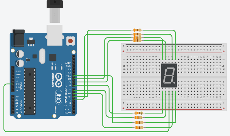
This circuit used 7 segment of common cathode type, so “GND” is connected to the common pin. So, 330 ohm resistors were used here.
| Arduino pin number | 7 segment pin number |
|---|---|
| 4 | 7(a) |
| 5 | 6(b) |
| 6 | 4(c) |
| 7 | 2(d) |
| 8 | 1(e) |
| 9 | 9(f) |
| 10 | 10(g) |
| 11 | 7(dp) |
| GND | 3 or 8(GND) |
code
In the code below, the “COMMON_CATHODE” was defined. Other than that, the other codes are the same. In case of common cathode, it turns on when 1, and turns off when 0.
1
2
3
4
5
6
7
8
9
10
11
12
13
14
15
16
17
18
19
20
21
22
23
24
25
26
27
28
29
30
31
32
33
34
35
36
37
38
39
40
41
42
43
44
45
46
47
48
49
50
51
52
53
54
55
56
57
58
59
60
61
62
63
64
65
66
67
#define COMMON_CATHODE
#if defined(COMMON_CATHODE)
#define NUM_0 {1, 1, 1, 1, 1, 1, 0}
#define NUM_1 {0, 1, 1, 0, 0, 0, 0}
#define NUM_2 {1, 1, 0, 1, 1, 0, 1}
#define NUM_3 {1, 1, 1, 1, 0, 0, 1}
#define NUM_4 {0, 1, 1, 0, 0, 1, 1}
#define NUM_5 {1, 0, 1, 1, 0, 1, 1}
#define NUM_6 {1, 0, 1, 1, 1, 1, 1}
#define NUM_7 {1, 1, 1, 0, 0, 1, 0}
#define NUM_8 {1, 1, 1, 1, 1, 1, 1}
#define NUM_9 {1, 1, 1, 1, 0, 1, 1}
#define DECIMAL_POINT (1)

#else

#define NUM_0 {0, 0, 0, 0, 0, 0, 1}
#define NUM_1 {1, 0, 0, 1, 1, 1, 1}
#define NUM_2 {0, 0, 1, 0, 0, 1, 0}
#define NUM_3 {0, 0, 0, 0, 1, 1, 0}
#define NUM_4 {1, 0, 0, 1, 1, 0, 0}
#define NUM_5 {0, 1, 0, 0, 1, 0, 0}
#define NUM_6 {0, 1, 0, 0, 0, 0, 0}
#define NUM_7 {0, 0, 0, 1, 1, 0, 1}
#define NUM_8 {0, 0, 0, 0, 0, 0, 0}
#define NUM_9 {0, 0, 0, 0, 1, 0, 0}
#define DECIMAL_POINT (0)

#endif

int num_array[10][7] = {
	NUM_0,
	NUM_1,
	NUM_2,
	NUM_3,
	NUM_4,
	NUM_5,
	NUM_6,
	NUM_7,
	NUM_8,
	NUM_9,
};


int count = 0;

/* 7 segment pin number */
int seg_port[] = {4, 5, 6, 7, 8, 9, 10};
unsigned long prev_millis = 0;


void setup() {
	for (int i = 0; i < sizeof(seg_port)/sizeof(seg_port[0]); i++) {
		pinMode(seg_port[i], OUTPUT);
	}

	pinMode(11, OUTPUT);
    digitalWrite(11, DECIMAL_POINT);
}

void loop() {
  for (int i = 0; i <7 ; i++) {
    digitalWrite(seg_port[i], num_array[count % 10][i]);
  }
  delay(1000);
  count++;
}
Leave a comment